 If a level railway track starts to rise or fall, a passing vehicle has to be
aligned to the resulting curve. This is done by defining two points of contact
between the vehicle (its wheels) and the track. The connecting line between these
points defines the inclination to be used for the vehicle body.
If a level railway track starts to rise or fall, a passing vehicle has to be
aligned to the resulting curve. This is done by defining two points of contact
between the vehicle (its wheels) and the track. The connecting line between these
points defines the inclination to be used for the vehicle body.
 If two single axes or two bogies exist, the real points of contact are used
or the central locations of the bogies are assumed as virtual points of contact. But
if irregular wheel arrangements exist or the vehicle consists of different
partial bodies like steam locomotives with separate tenders or the
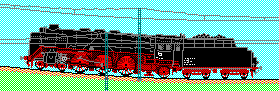
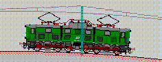
"three-room-appartment with wheels" E 91, this method will not succeed.
Here, additional information is necessary to calculate the appropriate points of
contact for correct inclinations.
If two single axes or two bogies exist, the real points of contact are used
or the central locations of the bogies are assumed as virtual points of contact. But
if irregular wheel arrangements exist or the vehicle consists of different
partial bodies like steam locomotives with separate tenders or the
"three-room-appartment with wheels" E 91, this method will not succeed.
Here, additional information is necessary to calculate the appropriate points of
contact for correct inclinations.
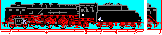
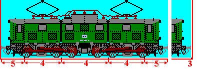 For this, the vehicle bitmap has an additional bottom line with control pixels
added as shown in the illustrations alongside.
For this, the vehicle bitmap has an additional bottom line with control pixels
added as shown in the illustrations alongside.
The control line, containing locations for points of contact as well as for boundary
points, can be recognized by the existence of a black pixel at the right lower
corner of the bitmap (3). Individual black pixels within the
control line identify points of contacts, where the straight connecting line between
such two points (to be drawn virtually along the track profile) defines the
inclination for the vehicle body (in the illustrations alongside, the single
inclination region between two points of contact is marked with
(4)).
If a vehicle body is overhanging (i.e. its edges are outside of the region between
the points of contact), the inclination for the outside parts (marked with
(5)) is not altered relative to the inside part of the vehicle
body. The overhang is delimited either by the boundary of the vehicle or by an
adjacent partial body of the same vehicle which has its own inclination.
In the latter case, the boundery between these two bodies is marked by a boundary
point within the control line which consists of two concatenated black pixels.
If the bitmap contains two side views of the vehicle, only the information for the
left part is needed. For the right part, the program uses the mirrored information.