 The horizontal size of a vehicle drawing for the program BAHNLAND depends on the
length of the original, where 10 cm in reality corresponds to 1 pixel
in the bitmap. The bitmap height is the distance between the rail track and the
overhead electric supply (catenary wire), which is standardised to
58 pixels.
The horizontal size of a vehicle drawing for the program BAHNLAND depends on the
length of the original, where 10 cm in reality corresponds to 1 pixel
in the bitmap. The bitmap height is the distance between the rail track and the
overhead electric supply (catenary wire), which is standardised to
58 pixels.
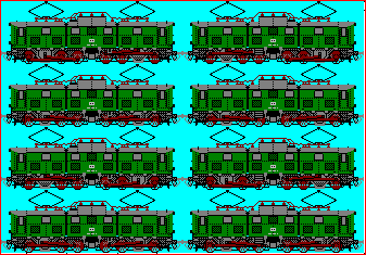
If there are different side views of the vehicle or if it is an asymmetrical
construction (e.g. like a steam locomotive), both side views are presented side
by side within the same bitmap. If there are moving parts (e.g. coupling rods),
the individual motion phases are presented one below the other, where the set of
motion phases from top to bottom corresponds to a movement of the vehicle from right
to left. The program BAHNLAND calculates the number of motion phases which have to
be distinguished from the total height of the bitmap. BAHNLAND provides up to
8 motion phases for one vehicle. For wheels, this corresponds to partial
rotations by 45 degrees.
![]()
![]() In addition to the real picture information, there is a control column at the right
and (in some cases) a control row at the bottom of the vehicle bitmap with further
information for the program BAHNLAND.
In addition to the real picture information, there is a control column at the right
and (in some cases) a control row at the bottom of the vehicle bitmap with further
information for the program BAHNLAND.
The black pixel marked with (1) signals the existence of two
side views within the bitmap. If a non-black pixel is found at this position, only
one side view of the vehicle is present. In this case, the other side of the
vehicle is assumed to be identical. Depending on the color of this pixel, the
program uses either the left or right half bitmap or the whole bitmap (excluding
the control column and the control row) for displaying the vehicle within the
landscape.
The vertical position of the second black pixel (marked with
(2)) specifies the motion phase length if more than one
motion phase exists (the position is calculated from the top of the bitmap,
counting up from 0; in the present example, a motion phase length of 7 is
specified). The program changes from one phase to the next after the picture was
moved by the motion phase length. For wheels to roll correctly, the motion phase
length should be calculated as the circumference of the wheel divided by the number
of motion phases (all lengths are measured in pixels).
The color of the corner at the top left (6) is interpreted
as the background color of the bitmap. This color must not be one of the vehicle
colors because all pixels with this color are made transparent when the bitmap is
positioned within the landscape by the program.
The horizontal control area at the bottom of the bitmap is described in the chapter Inclines.